MOD Web GUI User Guide
This page describes the graphical user interface (GUI) that is used for installing and removing plugins, setting up your pedalboards and banks, sharing pedalboards, updating your MOD devices and more.
Contents
- 1 Accessing the GUI
- 2 Creating a pedalboard
- 2.1 New pedalboard
- 2.2 Adding and connecting plugins
- 2.3 Adjusting plugins parameters
- 2.4 Assigning plugins parameters
- 2.5 Saving / loading pedalboard snapshots
- 2.6 Saving a pedalboard
- 2.7 Organizing Banks
- 2.8 Installing new plugins
- 2.9 Sharing a pedalboard
- 3 Expanding Controls
- 4 True Bypass
- 5 CPU Usage
- 6 Settings
Accessing the GUI
Connect your MOD device to your PC or Mac using the USB cable which you received with your device. The operating system should recognize your unit as a network device and configure it automatically. However, this process may fail in certain Windows versions, if that is your case please check the troubleshooting page.
Then open your favorite browser and navigate to
For the MOD Duo: http://modduo.local or http://192.168.51.1.
For the MOD Duo X: http://modduox.local or http://192.168.51.1.
If you are connecting via BlueTooth, visit http://192.168.50.1.
Creating a pedalboard
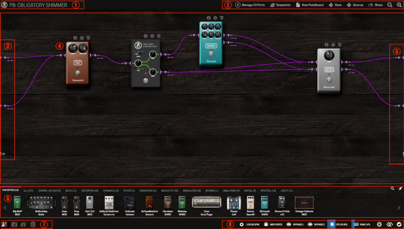
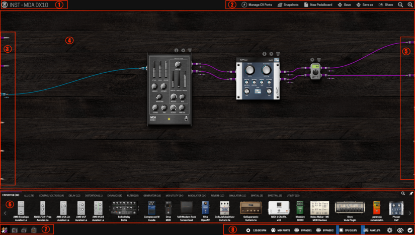
Once you have accessed the GUI you should see a screen like these:
| MOD DUO | MOD DUO X |
|---|---|
 |
|
The numbered areas on the interface are:
- Pedalboard name
- Pedalboard actions bar
- Inputs
- Pedalboard assembler
- Outputs
- Plugins bar
- Mode selector (Constructor, Pedalboards, Banks and Store)
- Status bar (Device actions and information)
| MOD DUO | MOD DUO X |
|---|---|
| On the left edge of the assembler area (section 3) of the MOD DUO Web GUI there are 3 connectors: 2 audio inputs and 1 MIDI input. | On the left edge of the assembler area (section 3) of the MOD DUO X Web GUI there are 5 connectors: 2 audio inputs, 1 MIDI input, 2 CV inputs and 1 expression pedal input. |
| On the right edge (section 5) there are another 3 connectors: 2 audio outputs and 1 MIDI output. All those connectors represent the real inputs and outputs of your MOD DUO. | On the right edge (section 5) there are 5 connectors: 2 audio outputs, 1 MIDI output and 2 CV outputs. All those connectors represent the real inputs and outputs of your MOD DUO X. |
Be aware that on the interface:
- the signal flows from left to right;
- purple cables transport audio signals;
- cyan cables transport MIDI signals;
- orange cables transport CV signals.
New pedalboard
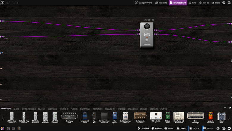
To create a new pedalboard click on the ![]() button in the pedalboard actions bar. This action will load the default pedalboard, which is a stereo gain connecting the audio inputs to the outputs.
button in the pedalboard actions bar. This action will load the default pedalboard, which is a stereo gain connecting the audio inputs to the outputs.
This is a standard behaviour both for the MOD DUO and the DUO X
Adding and connecting plugins
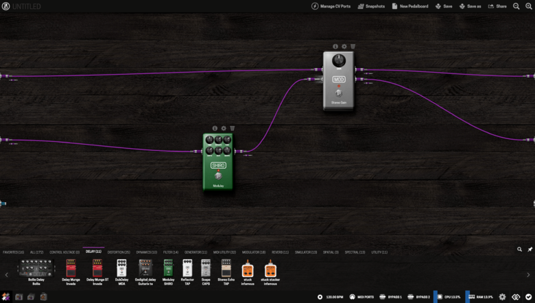
To add plugins, drag-and-drop one from the plugins bar to the pedalboard assembler area. To make a new connection, click on the plugin’s output jack and drag it to where you want to connect it to. To unmake a connection, click on the connected jack, then drag and release it to any empty area on the assembler.
Note that the inputs and outputs of your device are completely independent and can process multiple audio paths. The MOD devices allow you to create multiple connections coming out from the same output and also allows multiple connections to come in the same input. This feature allows the user to create complex pedalboards.
Adjusting plugins parameters
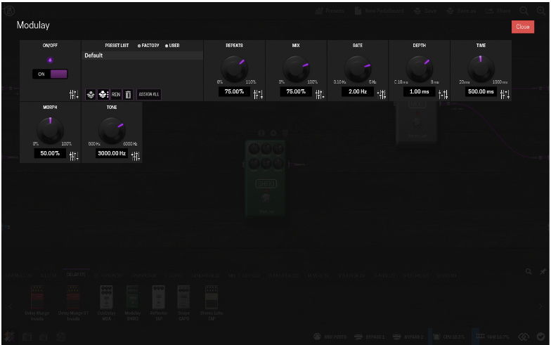
Each plugin has 3 icons on its top: info ![]() , settings
, settings ![]() and delete
and delete ![]() . To adjust the parameters of the plugin click on the settings icon.
. To adjust the parameters of the plugin click on the settings icon.
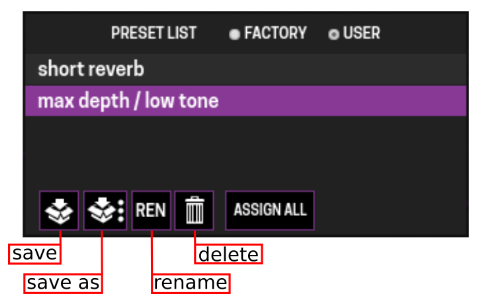
Each knob, list and switch represents a parameter of the plugin and can be adjusted as desired. The combination of all parameter values can be saved/loaded as a user preset and, for the cases in which they are available, factory presets can be loaded.
Assigning plugins parameters
One of the most powerful features that MOD devices offer is the ability to assign plugin parameters and preset lists to physical actuators, like knobs, buttons and footswitches.
Any parameter can be assigned, but some parameters can only be assigned to a specific type of actuator. The interface will not show the actuator as an option if it is not allowed to be assigned to. Note that preset lists can also be assigned to actuators.
To create an assignment, first click on the fader icon ![]() , found on the bottom-right corner of each parameter box, to open the assignment dialog box. For the presets list you must click "Assign All" and you must have your list populated with more then one preset.
, found on the bottom-right corner of each parameter box, to open the assignment dialog box. For the presets list you must click "Assign All" and you must have your list populated with more then one preset.
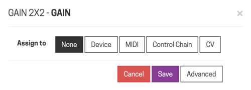
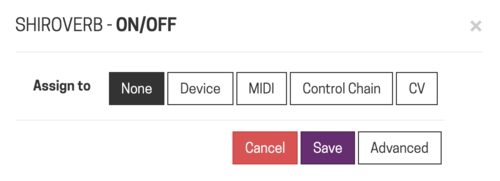
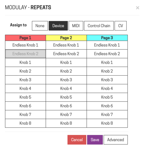
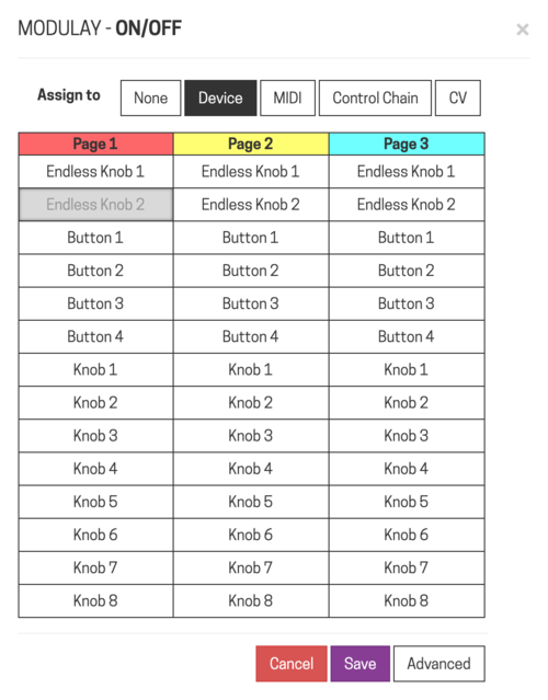
It will popup a window with multiple lists, similar with the following:
Removing an assignment
If you want to remove an assignment just select "None" tab and press save.
Making an assignment to a MOD DUO actuator
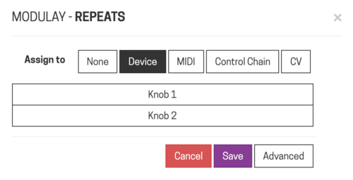
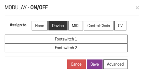
If you want to make an assignment to one of the endless knobs or footswitches of your MOD DUO select the tab "Device".
Afterwards, select the actuator you would like to assign the parameter to from the correspondent lists.
Note: the knobs of the MOD DUO can hold multiple assignments but footswitches can only hold one.
Making an assignment to a MOD DUO X actuator
If you want to make an assignment to one of the endless knobs, knobs or buttons of your MOD DUO X select the tab "Device".
On the MOD DUO X, you have a pagination system (learn more about it here and here) that allows you to assign multiple parameters to each of the actuators (endless knobs, knobs and buttons).
To switch between these pages you should use the performance buttons.
Select on this window the actuator that you want to assign.
Making an assignment to a MIDI Controller
If you want to assign any type of parameter to an actuator of an external MIDI Controller you much select the "MIDI" tab, press save and interact with the desired actuator (for example: push the button or turn the knob).
Making an assignment to a Control Chain Device
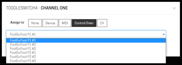
If you want to assign a parameter to a control chain device (like the MOD Footswitch or the Arduino Shield) select the tab "Control Chain".
You will get a dropdown list with all the actuators that you have on the control chain connected to your MOD device. Select the one that you wish to assign.
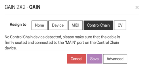
Note: if you have no control chain devices connected to your MOD device you will get the following message:
For more info check Control Chain
Making an assignment to a CV controller
If you want to assign a parameter to one CV controller connected to your MOD device select the tab "CV".
MOD DUO X
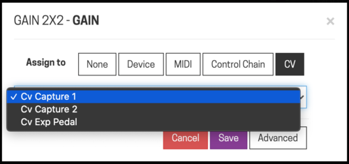
For the MOD DUO X users, on the CV window you will have a dropdown list already filled with the hardware CV/EXP input showing up as a CV addressing source.
Select from there if you want to use an expression pedal or one of the two CV inputs.
Other MOD devices
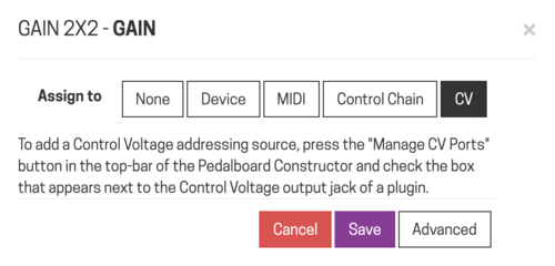
For other MOD devices it is necessary to create an internal CV addressing source.
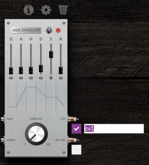
- For that you need to load one CV plugin from your plugins bar.
Note: if you have no Control Voltage plugins available on your plugins bar, head over to the shop and you will find pretty cool ones for free.
- Two squares will appear on the right side of the CV plugin that you've just loaded. Select and label the ones that you want to use.
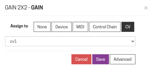
- This way you just created an internal CV controller. Head back to the CV tab of the control you want to assign and now you will be able to see a dropdown menu with the labels that you just created on your CV plugins.
Advanced Settings
There is also the possibility to adjust further options by clicking on the "Advanced" button.
By clicking on it your assignment window will stretch.
Here you can:
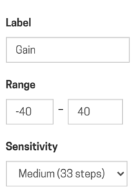
- Define a different label that you would like to be displayed on the displays of your device;
- Enter the range that you want the mapped actuator to sweep within;
- Set the sensitivity (amount of steps from minimum to maximum) of the actuator from the dropdown menu;
- Set the operational mode polarity of your CV control.
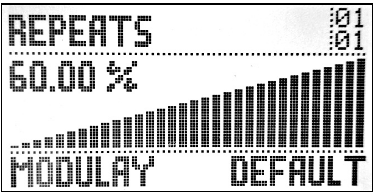
Once you have done the adjustments, click on the save button to execute the assignment. At this point you should see the assigned information on the display and be able to operate the parameter through the actuator you have chosen.
TODO: Get version of this image on the DUO X and replace this one with other background
Saving / loading pedalboard snapshots
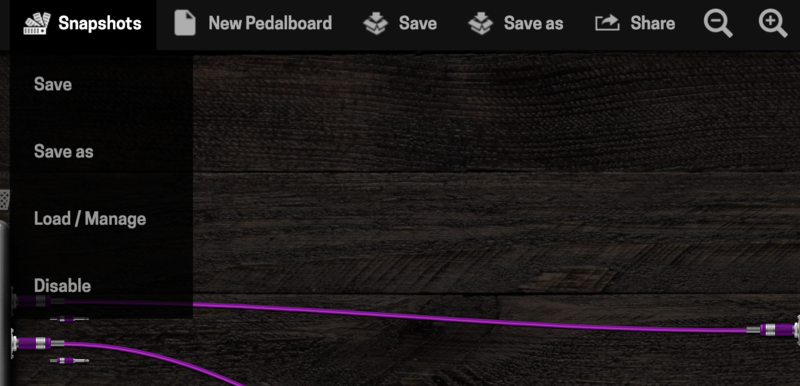
You have the possibility to save the combination of parameter adjustments as a pedalboard snapshot. In order to do so, turn on the pedalboard snapshot mode by clicking on the snapshot button ![]() , positioned on the pedalboard actions bar.
, positioned on the pedalboard actions bar.
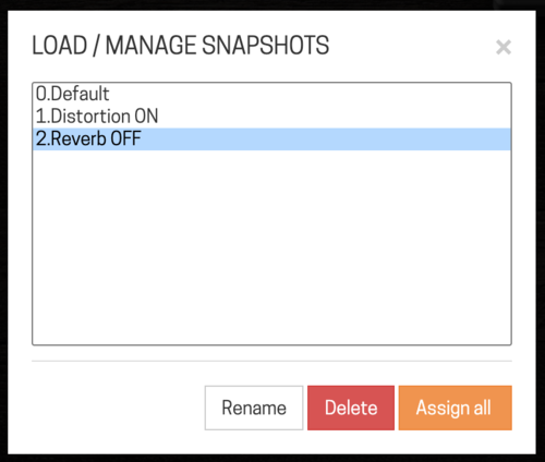
To save the changes to the current pedalboard snapshot, choose the option Save. To save a new snapshot use the option Save as and give it a name. To load, delete or rename a saved snapshot use the option Load / Manage.
A single click on the name of the snapshot will load it. You also have the option to assign the snapshots list to an actuator by using the Assign all button.
Another way to navigate the snapshots is using an external MIDI controller connected to your MOD device.
NOTE: the snapshot list currently cannot be reordered, so some care must be taken when saving new shapshots in ordered to be effectively navigated with an actuator or via MIDI.
Saving a pedalboard
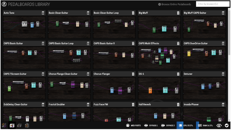
To save a pedalboard use the buttons Save or Save as on the pedalboard actions bar. All previously saved pedalboards can be found and loaded from the pedalboards library. To access the pedalboards library click on its button ![]() in the mode selection bar.
in the mode selection bar.
A single click on the pedalboard image or name will load it to the assembler. To delete a pedalboard click on its trash icon ![]() on the right of the pedalboard name.
on the right of the pedalboard name.
Organizing Banks
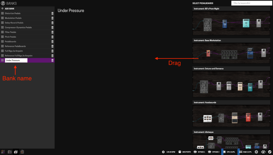
In order to make it easy to access your pedalboards while the MOD device is disconnected from your PC, Mac or tablet, you can organize your pedalboards in banks. To access the banks configuration click on the banks icon ![]() in the mode selection bar.
in the mode selection bar.
In the banks configuration mode, use the ![]() button to create a new bank and name it as you like. At this point your bank is empty and ready to receive your pedalboards. To add pedalboards to your bank drag them from the right lateral panel into the center of the screen. You can add as many pedalboards as you want. It is also possible to add multiple instances of the same pedalboard to your bank.
button to create a new bank and name it as you like. At this point your bank is empty and ready to receive your pedalboards. To add pedalboards to your bank drag them from the right lateral panel into the center of the screen. You can add as many pedalboards as you want. It is also possible to add multiple instances of the same pedalboard to your bank.
You can now navigate through your banks using the Device Menu.
On the MOD Duo, you can also use the Footswitches to navigate through the pedalboards of a bank. In order to do it just active the option "Foot Nav" on teh Settings of your MOD Duo.
Installing new plugins
By default MOD devices come with many plugins installed, but you can install even more. The plugins available for download for MOD devices are created either by the MOD team, or by independent developers. To learn more about plugins please check the Advanced Information chapter.
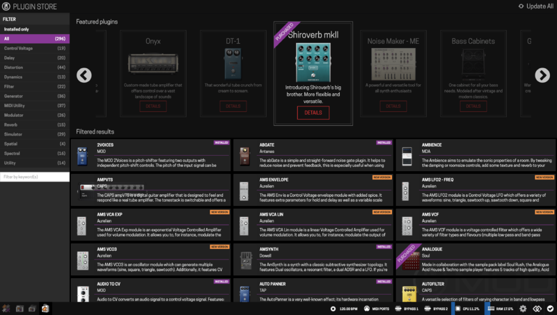
In order to install new plugins you need to access the plugin store by clicking on its icon ![]() in the mode selection bar. After you have accessed the store you can look for the plugin you want by filtering by category or typing a keyword in the search box.
in the mode selection bar. After you have accessed the store you can look for the plugin you want by filtering by category or typing a keyword in the search box.
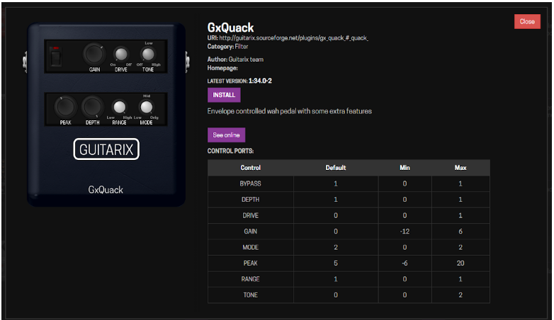
Once you have decided which plugin you want to install, click on it to open the description dialog, and then click on the install button. The plugin will be automatically downloaded and installed on your device. You can also remove or upgrade an already installed plugin by clicking on the corresponding button.
Sharing a pedalboard
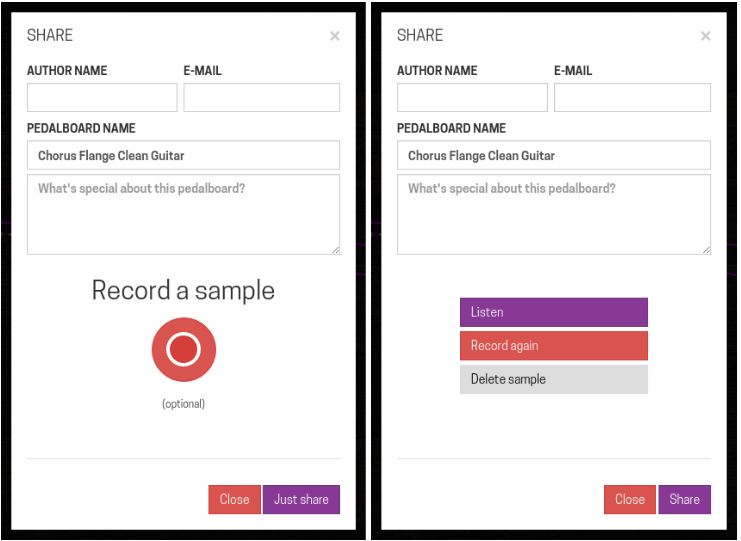
Another great feature that the MOD devices have is allowing you to share and load pedalboards from the existing MOD online community. To share a pedalboard, go to the pedalboard assembler and click on the share ![]() button in the pedalboard actions bar. Fill in the sharing dialog and (optionally) record a sample by clicking on the red circle. After finishing the recording, you can listen to it, or record it again. When you are done, click on the Share button.
button in the pedalboard actions bar. Fill in the sharing dialog and (optionally) record a sample by clicking on the red circle. After finishing the recording, you can listen to it, or record it again. When you are done, click on the Share button.
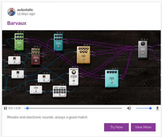
To load pedalboards from another MOD user, visit: https://pedalboards.moddevices.com, listen to the samples and once you find a pedalboard you like, click on the Try Now button. Note that in order to load an online pedalboard, you need to have the MOD GUI opened.
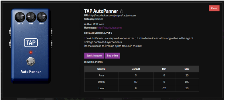
Use the View More button to see what plugins were used to create the pedalboard. Additionally you can list the pedalboards that were made using a specific plugin. In order to do this, open the plugin description dialog (for example by clicking on the
![]() info button on the top of the plugin), and then click on the See it in action button.
info button on the top of the plugin), and then click on the See it in action button.
Expanding Controls
MIDI devices
There are two ways to connect MIDI devices, via the classic MIDI DIN connector and via USB.
MIDI DIN - Input
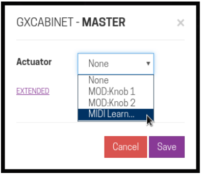
To use the MIDI DIN simply connect your device to the MIDI Input and use the MIDI Learn function to assign a control to a plugin parameter (see #Assigning plugins parameters to actuators).
Once you selected and saved the MIDI Learn function go to your MIDI device and operate the actuator you want to control the parameter. At this point you should be able to control the plugin parameter using your MIDI device.
MIDI DIN - Output
Some plugins have MIDI output ports, which generate MIDI output data like control change messages and notes. You can use this output to send this data to your other equipment.
MIDI USB
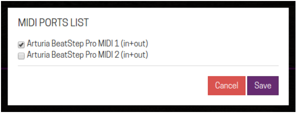
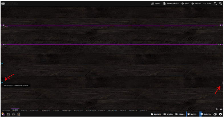
In addition to the classic MIDI ports you can also use the USB port to connect your MIDI controllers. Your MOD device will recognize your MIDI device when it is plugged in and add it to the MIDI ports list. Because a single MIDI device can have multiple ports, they are not visible in the assembler by default. To make them visible you will have to enable them first by clicking on the MIDI ports ![]() button.
button.
On the MIDI ports list select the ports that you want to enable and click on the Save button. Now you should see the new ports added to the assembler screen.
Note that you do not have to enable a specific MIDI port to be able to use MIDI learn. For MIDI learn, all MIDI devices will work as soon as they are connected to your MOD device.
True Bypass
The MOD devices have a true bypass circuit for each pair of input/output. This allows you to physically connect input 1 to output 1, and input 2 to output 2. The true bypass is enabled when the device is off and it is automatically disabled after the current pedalboard is loaded.
You can enable or disable the true bypass via the GUI using the two bypass buttons
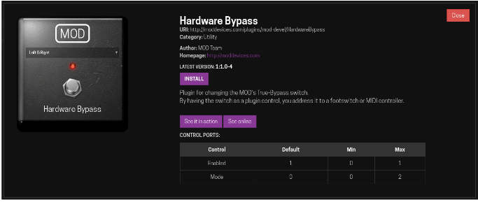
![]() in the status bar. As a second option, you can control the true bypass using a special plugin called Hardware Bypass.
in the status bar. As a second option, you can control the true bypass using a special plugin called Hardware Bypass.
Install the Hardware Bypass plugin via the plugins store (see Installing new plugins section) and add it to your pedalboard. Now you can assign the ON/OFF parameter to any physical actuator (see Assigning plugins parameters to actuators) and control the true bypass with it.
CPU Usage
In the status bar of the GUI there are CPU and RAM meters. It is useful to monitor these resources when you are creating your pedalboard. It’s recommended to keep the CPU usage lower than 80%. Note that each plugin consumes a different amount of CPU and RAM.
Settings
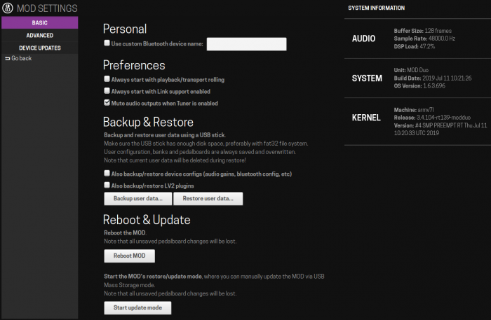
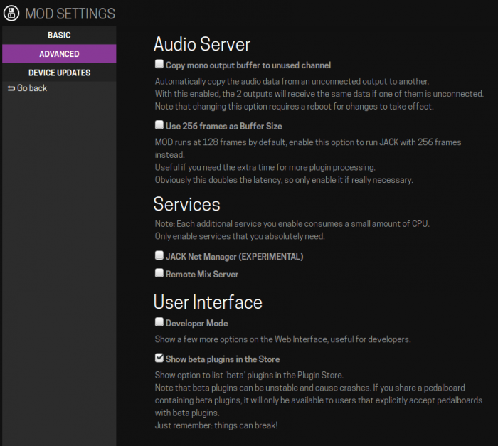
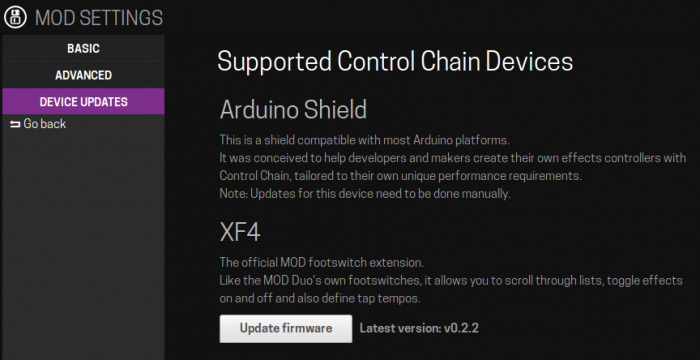
The "engine" button at the status bar will open the Settings page.
System Information
At the right hand side you will find information about your device configuration. Audio settings, system specification and software versions.
Basic Settings
Personal
- Use custom Bluetooth device name: If you are connecting to your device through a Bluetooth network, you may choose here the name you want your device to have.
Preferences
- Always start with playback/transport rolling: Automatically plays playback/transport when you turn your device on
- Always start with Link support enabled:
- Mute audio outputs when Tuner is enabled: Disables any audio output while you are using the Tuner
Backup & Restore
This feature allows you to make a backup of all your data to later recovery. You can backup Banks, Pedalboards, Device configuration (such as audio gains, Bluetooth config, etc) and all the plugins you have downloaded.
Creating a Backup
Insert a USB stick in the USB Host port (A) in the back of your unit. Make sure the USB stick has enough disk space, preferably with a fat32 file system.
By default, user configuration, pedalboards, and banks are included in the backup. Mark the correspondent checkboxes if you want to also backup the plugins you have installed and all the device settings, such as input and output gain.
Finally, click "Backup user data..."
Restoring a backup
Insert the USB stick in which you did the backup in the USB Host port (A) in the back of your unit.
Click "Restore user data..." and wait for the process to finish.
Note: You may have to reboot your device to be able to load the recovered data.
Reboot & Update
Here you can reboot your device and also restart it into restore/update mode for maintenance and manual updating.
