Arduino distance sensor tutorial
This tutorial shows how to build a Control Chain device with a distance sensor as seen in this Instagram video.
WHAT DO I NEED?
- One Arduino Uno or Due
- One Arduino Control Chain shield
- One HC-SR04 Distance Sensor (or any other ultrasonic sensor, they mostly work the same way)
- Some soldering tin
- Some wire
- (Optional) Some 10K linear potentiometers
- (Optional) Something to put your build in
THE SCHEMATIC
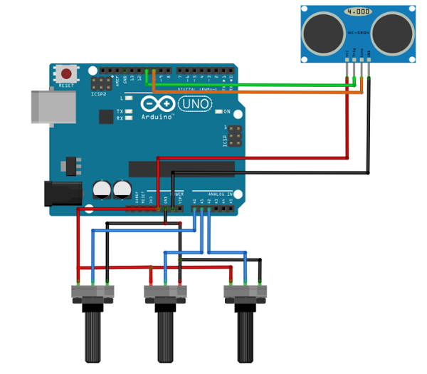
The schematic of this build is quite straightforward. The sensor has 4 pins; VCC, GND, Echo and Trigger. These are connected to the Arduino shield.
For this example, 2 potentiometers are used for the minimal and maximal values that the sensor measures. Also, another potentiometer is used as a ‘sensitivity’ potentiometer.
Notice the brackets on sensitivity, because this variable does not change the behavior of the sensor at all. It only controls a weighted average filter function in the code. This filter smoothes out inaccurate measurements that may occur in the sensor. THE CODE
When I started making this code, I could not delay the main program for longer than a few milliseconds because I was using an older version of the Control Chain library. The libraries that are often used for this sensor, do delay the main loop for too long. Reading through the datasheet/library however, gave a better insight on how the sensor works.
Now the PulseIn function is used to manually read/write to the trigger and echo pin of the distance sensor. Using the Control Chain library version 0.5.0 and up, you can just use the library from the sensor manufacturer, but because we can do it manually let’s leave it like this. It saves up some memory on the Arduino!
At the beginning of the code, there is a #define that you can use to invert the way the distance corresponds to the actuator. By setting this #define to 0, the smaller the distance, the lower the actuator’s value. When this #define is set to 1, the smaller the distance, the bigger the actuator’s value. When playing around with this in the office, we found that it is really a matter of preference so that's why we left it easily changeable in the code.
THE BUILD
- Solder the Vcc pin of the sensor to the +5 track of the CC shield
- Solder the Ground pin of the sensor to the GND track of the CC shield
- Solder the echo pin to the corresponding digital pin (by default pin 10) of the CC shield
- Solder the trigger pin to the corresponding digital pin (by default pin 11) of the CC shield
- (Optional) Solder the potentiometers outer pins to +5V and GND of the CC shield
- Solder the potentiometers inner pin to the corresponding analog input of the CC shield (by default A0, A1 & A2)
UPLOADING THE CODE
1. Follow the instructions on our Github page and install the dependencies.
2. Change the defines to your preference and if you don’t want to use potentiometers change the analogRead() functions with constant values like this:
Line 88: PotValue = 0.5; //((analogRead(A0)/1023.0);
Line 124: MINDISTANCE = 20; //map((analogRead(A1)), 0, 1023, 5, 20);
Line 125: MAXDISTANCE = 50; //map((analogRead(A2), 0, 1023, 20, 65);
In line 88 you set the 'sensitivity' of the sensor between 0 and 1. In line 124 and 125 you can set the minimal and maximal value of the sensor in centimeter.
3. Upload the code to your Arduino
4. All done, time to test!
5. Connect the CC shield to your MOD Duo. If everything went well you should see a new CC device popping up
Control Chain device on MOD GUI Success!
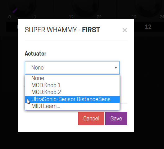
6. Assign the plugin parameter of your choice to the CC device actuator.
Ultrasonic sensor addressing Address it like any actuator on the GUI
7. Voilà! You should have an up and running distance-controlled actuator.
THE FINAL PRODUCT
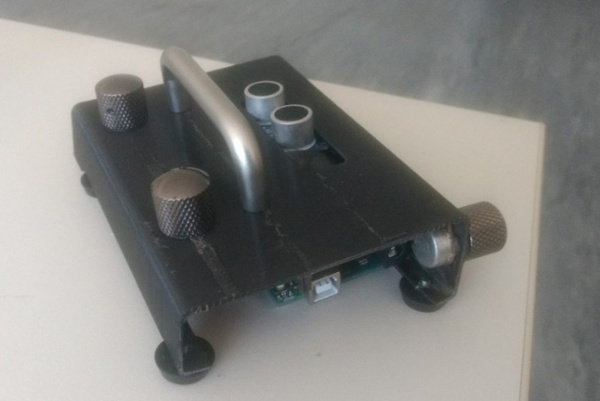
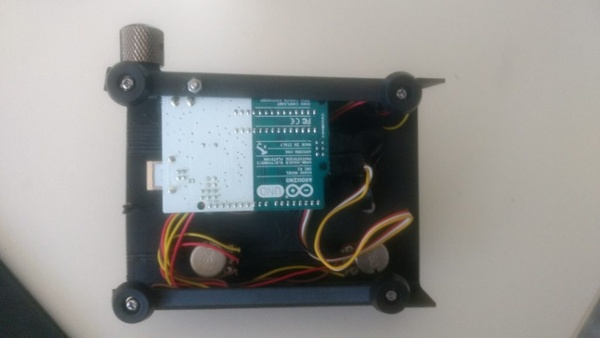
Ultrasonic sensor in a box Our own custom build with XF4 prototype scrap
(Optional) You can put your build in a cool box, I used some old 3D-prints which were used for the XF4 prototypes. It seemed like a nice fit!
Note: This tutorial was originally published by Jesse Verhage at the Mod Devices blog


